Three Way Valve Air Handling Unit

Fcu Ahu Applications Of 2 Way And 3 Way Valves Hvac System Youtube

Learn More About Hvac Three Way Valves Industrial Controls

Variable Flow In Hydronic Systems With Three Way Control Valves

Hvac Tech School 2 Way And 3 Way Control Valves For Ahu And Fcu Youtube

Mixing Valve An Overview Sciencedirect Topics

Transcold

Vent thru roof detail.
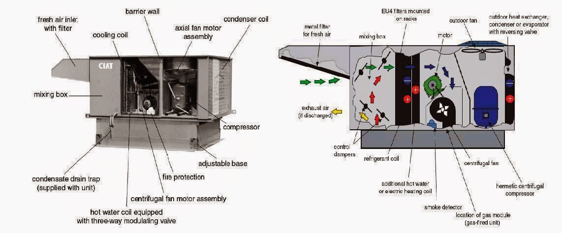
Three way valve air handling unit.

Baelz Control Valves 2 Way And 3 Way Youtube
Air Handling Units Explained The Engineering Mindset
Module 101 The Evolution Of Fan Coils For Efficient Conditioning Of Room Air Cibse Journal

How Does The Three Way Control Valve Working

Air Handling Unit

Victaulic Koil Kit Coil Packages For Air Handling Units Koil Kit Coil Packages Hydronic Balancing Flow Control Equipment Modules

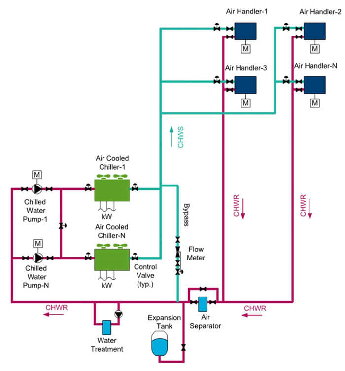
Chilled Water Schematics The Engineering Mindset

12v 220v 2 3 Way Spdt Fan Coil Unit Motorized Control Valves With Electric Actuator

Sizing Of Air Handling Unit Engineering Solutions Innovate
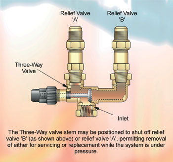
Masterclass Pressure Relief Safety Devices Part 18

Ahu Air Handling Unit System Of Hvac Heating Repair Furnace Repair Furnace Troubleshooting

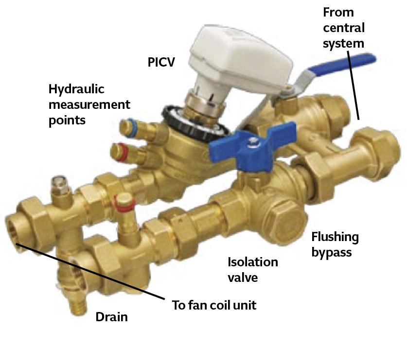
Ahu Valves Actuators Honeywell Pressure Independent Control Valve V5011p1038 K9 Wholesale Distributor From Aurangabad

Ahu Hookup
Chilled Water Pump Design Guide How To Size And Select A Chilled Water Pump
A Schematic Diagram Of A Fan Coil Unit Of Three Pipe System Redrawn Download Scientific Diagram
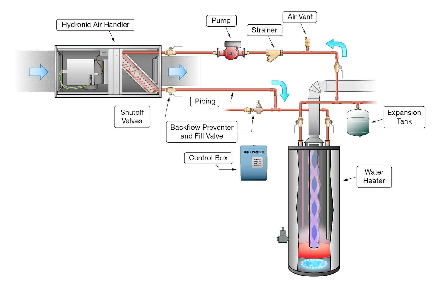
Basic Hydronic Heating Components And Their Role In A System Contracting Business

What Is Hvac Basic Of Heating Ventilation And Air Conditioning Hvac Meaning Hvac Stands For Heating Ventilation And Air Condit Hvac System Hvac Hvac Design
Air Handling Unit Fresh Air Handling Unit Calculations
Https Encrypted Tbn0 Gstatic Com Images Q Tbn 3aand9gctfxipid2tvepdqnbz9dh0idlnqs Giwomyki0jd8a9orzu6ept Usqp Cau

Image Result For Ahu Layout Refrigeration And Air Conditioning

Resilient Seated Butterfly Valves Ny Ab Series Bray Commercial Division

Air Handing Unit The Unit Flexible Joint Pressure Gauge

Schematic Of Mitsubishi Heat Pump Ac System 27 Download Scientific Diagram

How To Install A Split System Air Conditioner 15 Steps
Source : pinterest.com
