Test Terminal Block Wiring Diagram

Unique Auto Wiring Terminals Diagram Wiringdiagram Diagramming Diagramm Visua Electrical Circuit Diagram Electrical Wiring Diagram Electrical Panel Wiring

Data Link Connector Wiring Diagram Automotive Repair Car Repair Service Automotive Mechanic

Unique 110 Punch Down Block Wiring Diagram In 2020 Diagram Engineering Honda

Wiring Diagram In 2020 Electricity Electrical Engineering Drawings

33 Wiring Diagram For Car Trailer Light Bookingritzcarlton Info Electrical Wiring Diagram Electrical Diagram Diagram

17 1969 Chevy C10 Engine Wiring Diagram Engine Diagram Wiringg Net In 2020 Chevy Trucks 72 Chevy Truck 67 72 Chevy Truck

A vertical terminal block wiring with ptv terminal blocks enhances the structure and overview of your control cabinet.
Test terminal block wiring diagram.

Pin On George

4 20ma Junction Box Versus Fieldbus Ff Junction Box Inst Tools In 2020 Junction Boxes Electrical Installation Electricity

10 1992 Toyota Corolla Electrical Wiring Diagram Wiring Diagram Wiringg Net In 2020 Electrical Wiring Diagram Diagram Repair Guide

Triumph Bonneville T100 Thruxton Scrambler Wiring Diagram Triumph Bonneville T100 Bonneville T100 Triumph Bonneville

Bmw E39 Engine Diagram Wiring Diagrams Instruction Fair With Bmw E39 Wiring Diagram In 2020 Bmw E39 Bmw Bmw E36 318i

Access Denied Chevrolet Camaro Repair Guide Camaro


Image Result For Gm Hei Distributor External Coil Circuit Diagram Alternator Body Diagram

Electrical Wiring Diagram Of Motorcycle Http Bookingritzcarlton Info Electrical Wiring Diagram Of Fuel Injection Electrical Wiring Diagram Motorcycle Wiring

Fuel Tank Pressure Sensor Problems And Check Engine Lights Sensor Fuel Car Maintenance
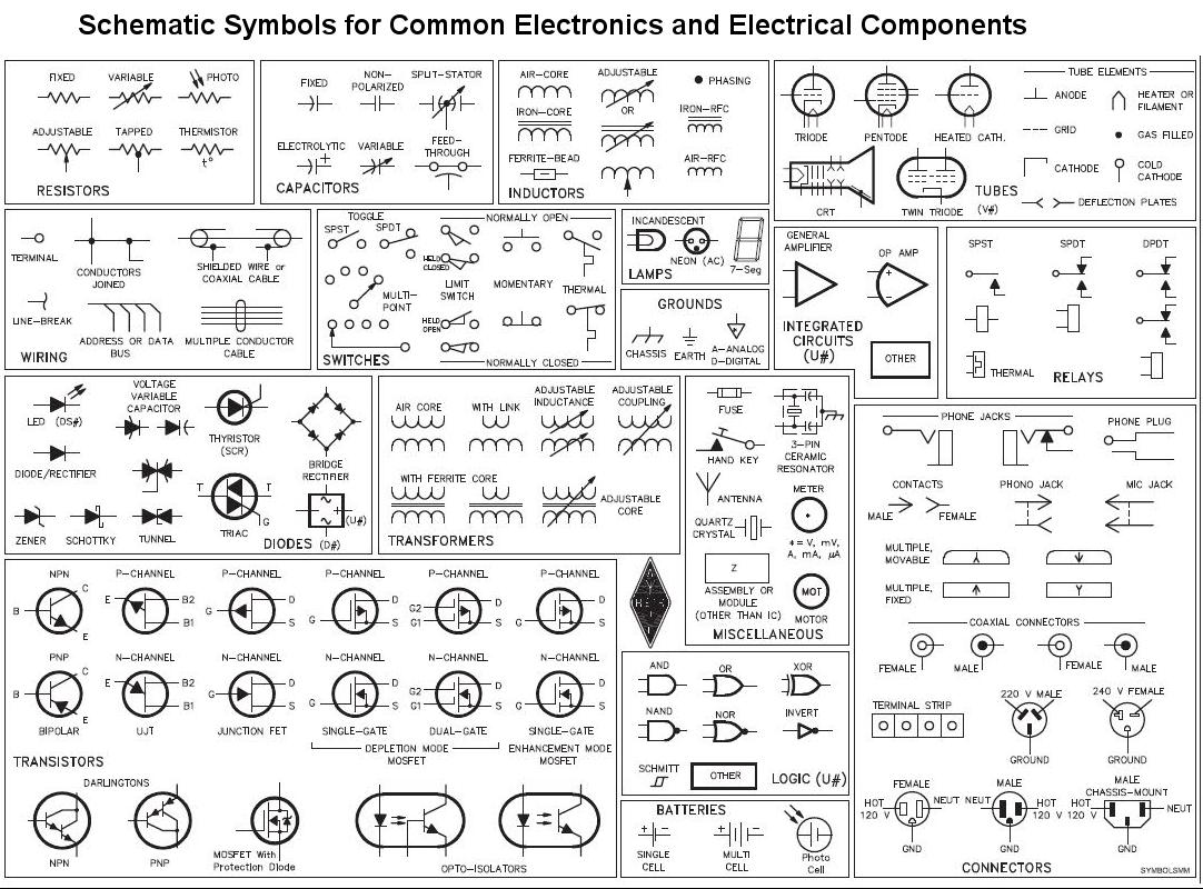
Circuit Schematic Symbols Electrical Schematic Symbols Electrical Symbols Circuit Diagram

Performing The Big 3 Wiring Ugrade On A 3rd Gen T4r A How To Toyota 4runner Forum Largest 4runner Forum 4runner Toyota 4runner Toyota

Hdmi To Vga Wiring Diagram Webtor Me Throughout Hdmi Cables Hdmi Picture Wire

Wiring Diagram Symbols Legend Http Bookingritzcarlton Info Wiring Diagram Symbols Le Electrical Symbols Electrical Wiring Diagram Electrical Circuit Diagram

Electric Ezgo Golf Cart Wiring Diagrams Ezgo Golf Cart Electric Golf Cart Golf Carts

Cat 5 Cable Connector Cat6 Diagram Wire Order E Cat5e With Wiring At Cat6 Cable Wiring Diagram Ethernet Wiring Cat6 Cable Computer Projects

E7 Engine Bay Diagram In 2020 Diagram Electrical Wiring Diagram Bmw E46

Reprap Prusa I3 Wiring Diagram And Wally The Ultimate Cost 3d Printer Diagram Build A 3d Printer
Https Encrypted Tbn0 Gstatic Com Images Q Tbn 3aand9gcrkufv11yrdcxbcei0dhxthwgmucxamnm9pr Ux Blgx R6ymad Usqp Cau

Diagram By Akita Your Diagram Source From Akita Automotive Electrical Relay Automotive Mechanic

Motor Forward Reverse Wiring Diagram Elec Eng World Electrical Circuit Diagram Electrical Wiring Diagram Basic Electrical Wiring
Pin On Wiring

3 Wire Alternator Wiring Diagram Lovely Wiring Diagram Denso Alternator Wiring Diagram Nippondenso Voltage Regulator Wiring Diagram Mobil Kereta

Pin On Electrical Wiring Diagram
Source : pinterest.com
